SOLIDWORKS TOOLBOX SCREWS HOW TO
If you did not catch this in the installation process this time now you know how to catch it next time around J **If you are installation savvy you may have already removed the un-needed Toolbox standards during installation process. The first page lists all of the standards, if you don't use some of them I would suggest that you uncheck them to help reduce the size and help users select the correct groups. OK enough about that… Open your Toolbox configurator and select Step 2.įirst off I would like to say there is a HUGE amount of information in this one section. If you are not sure where your Toolbox is located go to Tools, Options, System Options tab, HoleWizard/Toolbox location. The default location is C:\SOLIDWORKS Data.

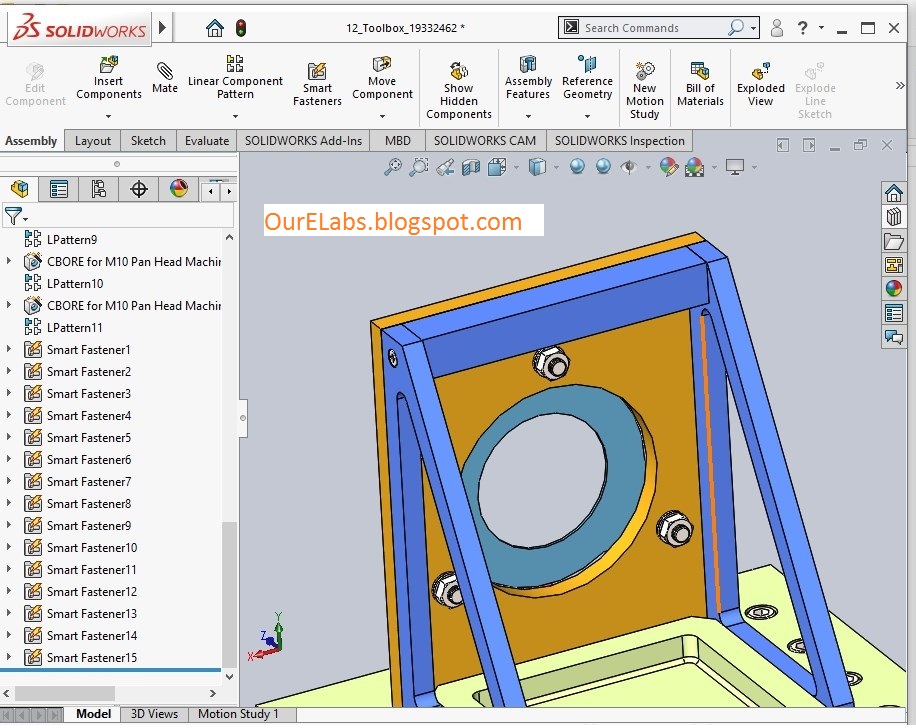
To be sure you have a good copy make sure to take the whole SOLIDWORKS Data folder. **As always please be sure to back-up your original Toolbox folder prior to making any changes. In this blog we will talk about Step2 Customize you hardware, which allows you to configure and customize your fasteners. (User no longer needs to edit toolbox definition in order to change fastener length.Welcome to Part2 of the SOLIDWORKS Toolbox configuration blog series. Dynamically change the length of the fasteners. Use Feature Driven Pattern to insert the washers and screws to the other 3 holes.** Feature Driven Pattern is able to support Hole Wizard Feature as well.Ĩ. Make use of the arrow to modify the length of the screw (30mm)ħ. From the context bar, size=M10 from property manager, Thread Display= Schematic. Drag in Socket Head Cap Screw ANSI B 18.3.1M from ANSI Metric > Bolts and Screws > Socket Head Screws. To add a new set of fastener size, click on the “add new row” button.Ħ. User will able to modify the existing fastener size. Click on “Size” under standard properties. Under 2nd page (Customize Hardware), click on my standard > Bolts & Screws> Socket Head Screws > Socket Head Cap Screw Ansi B18.3.1M. Enter my standard (as example) as the name of the new standard.ĥ. Under 1st page (Select Hardware), select Ansi Metric from Toolbox Standard, click on ‘Copy Standard” icon. To access the Toolbox configure window again, user can go to Toolbox> Configure… To Have Your Own Standard Toolbox! You can’t directly modify the existing toolbox in SolidWorks, what you need to do is to copy another set from the existing standard and modify the copy base own your own requirement. From the property manager, define brass as the material. From the context bar, define M10 as the size. Use the auto mate function to locate the washer. From toolbox browser, drag in the Plain washer. Save the changes and close up the window.ģ. Click OK and tick the check box for material. Under the value, key in Steel, Brass & Nylon. Under material column, browse in Plain Carbon Steel, Brass & Nylon. Property Name= Material Type= List Link to SW Material. Click on the 2nd tab- Customized hardware Navigate to the Narrow Flat Washer Ansi B18.22 M. A toolbox configure interface will appear. Select Ansi Metric > Washers > Plain Washers > Narrow Flat Washer Ansi B18.22 M. Click on the Toolbox under Design Library.


Here i would like to share some steps on how to configure your own toolbox by using the globe valve model:ġ. Since 2009, SolidWorks Toolbox has changed a new user interface which is much more user friendly.


 0 kommentar(er)
